The bell crank is expected to be made of steel which has yield strength of 250MPa and youngs modulus of 200GPa. The bell crank shown in III-2 is basically symmetric.

Push Rod Bell Crank Suspension Super 7th Heaven
A basic representation of bell crank is described.
. This phase concludes in safe bell-crank designs with factors of safety 488 and 33 and weight reduction of 794 and 74 for front and rear bell-cranks respectively with AISI 1018 as the chosen material. The cranks weight was reduced to 140 grams which is a 24 weight loss also the load required to plastic deform the component was increased to 159 kN which is 30 more that previous design. The Lafayette formula hybrid car currently contains a double A-arm configuration with a pushrod operated bell crank front suspension and a double A-arm with a linear coil over shock design.
The proven design is a type of inboard pushrod suspension when space is limited and the shock cannot be mounted in the most beneficial location. The bell crank is also designed on the basis of suspension geometry made by taking the hard points. Typical example of a bell crank 2 20 Initial Load Case.
A bellcrank is a type of crank that changes motion through an angle. 20-Es suspension was designed with this in mind seeing adjustability and data collection as a critical point of improvement for future cars. After finding the bellcrank forces the dimensions of the bellcrank and the associated OEMs bearings are calculated and found.
Bell Crank Design 3 The bellcrank that you design will need to fit the exact ball bearing ball joint linkages and spring shown in the supporting information. Suspension assembly of a F3 car highlighted featuring the pushrod bell-crank purple and spring-damper The bell crank also allows the magnitude of leverage generated by the system to be customised to the application at hand but importantly for us it introduces non-linearity into the leverage which will be the subject of the rest of this. The cause of accidents due to suspension failure is fatigue.
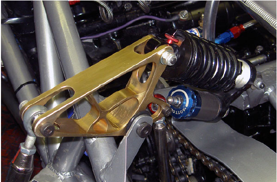
One feature that makes this particularly easy is the bell crank as we see below. Bell crank or rocker arm is basically the link between push rod and the damping mechanism. To overcome the unequal load distribution which occurs with the reactive balance beam suspension when either driving or braking a.
As a master thesis study a Formula SAE cars bell crank was topology optimizedThe bell crank is highly stressed the largest load acting on it being 3500 N. In Chapter 8 suspension dynamicswe shall see that a rising rate suspension is desirable and it is common to make use of the necessary suspension geometry to produce a rate that is rising naturally as a result of the suspension design. As bell crank lever is subjected to heavy loads and stresses and it is necessary to find out the safe load and the best Material which under required conditions can fulfil the work criteria.
Formula-style racer car The Bell crank lever is. Rod and bell crank to control the suspension system. The goal of this project was to design a bell crank for an FSAE prototype to withstand fatigue loads and reduce the chances of failure.
The multi-link suspension has one control extra rod also called a PullRod linking the Upper end. The new design used two road wheels on a single bogie each connected to a bell crank with a horizontal coil spring between the crank arms and double-acting shock absorbers to control recoil. The cause of accidents due to suspension failure is fatigue.
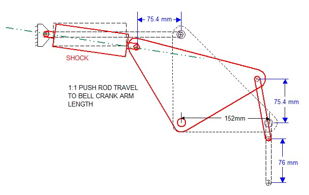
This design makes use of a push rod and bell crank to provide a more advantageous motion ratio for the shock and spring. The angle can be any angle from 0 to 360 degrees but 90 degrees and 180 degrees are most common. Opposed to the normal type outboard suspension the inboard design transmits the wheel forces through a pushrod and.
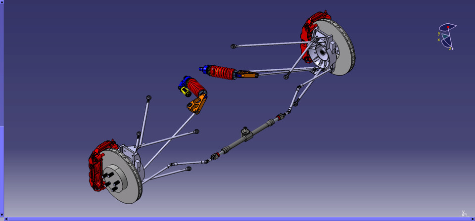
Introduction 1 What is Suspension System. An inboard mounted spring a push rod and a bell crank assembly. A-Arms Bell Crank Pushrod Ansys Spring and Dampers 1.
The goal of this project was to design a bell crank for an FSAE prototype to withstand fatigue loads and reduce the chances of failure during its use. The cause of accidents due to suspension failure is fatigue. Positioning of related parts.
Its function is to transfer force from push rod to spring dampers. I Identify the data information and gathering literature review for bell crank and suspension system ii Design several concept designs and making a design selection iii Find a suitable and good material that suit the bellcrank iv Analyze the effectiveness of the bell crank functioning for front suspension. Figure III-2 shows details of the exact positioning of the components.
The goal of this project was to design a bell crank for an FSAE prototype to withstand fatigue loads and reduce the chances of failure. This was fitted to the A6E3 between February and April 1935 and immediately proved to dramatically improve stability. The third phase includes the material selection design simulation and optimization of bell-cranks.
CAD Model of In-line Bell crank thus the results are taken to be as Figure 2 shows the design of the in-line bell crank. The Suspension system is a device connecting the body with wheels. The bell crank is made of mild steel.
This article deals with design of Formula SAE Suspension by considering various loads and their simulation on each component of the system. With suspension design relying heavily on the fidelity of vehicle dynamics modeling Formula SAE teams with no experience in this subject leverage track data from previous cars to drive design iterations. It is key that we identify key parameters for intended performance test the current suspension to see if these parameters can be met and modify the.
The bell crank is. The name comes from its first use changing the vertical pull on a rope to a horizontal pull on the striker of a bell used for calling staff in large houses or commercial establishments. A bell crank sometimes depicted as rocker arm aids in transferring bump and droop motion during vehicle translation from wheels via pushrod to suspension dampers in order to ascertain healthy ride comfort.

Bell Crank Push Rod Suspension System Youtube

The Bell Crank In Assembly Download Scientific Diagram

The Original Bell Crank Download Scientific Diagram

Bellcrank Suspension Design 3d Cad Model Library Grabcad
Post 41 Cranking Up The Shocks

Push Rod Bell Crank Suspension Super 7th Heaven
Bellcrank Suspension Design 3d Cad Model Library Grabcad
Formula Sae Car Bell Crank Topology Optimization Guide
0 comments
Post a Comment